
About MediaChance
Products
Links
Woodworking CNC routers become quite popular in the last decade or so. Here is my quick way how to use them
for creating PCB, very fast and reliably.
If you ever tried to make PCB on a woodworking router you will encounter two problems:
•
lack of precision
•
large amount of time to remove material between lines
My method outlined here tries to address both of these issues.
The trick is that instead of normal PCB where we have thin routes with large copper space removed between
them, we do an “isolation” PCB: we remove only thin space between large pads of copper. The process to create
this from normal PCB typically uses Voronoi algorithm.
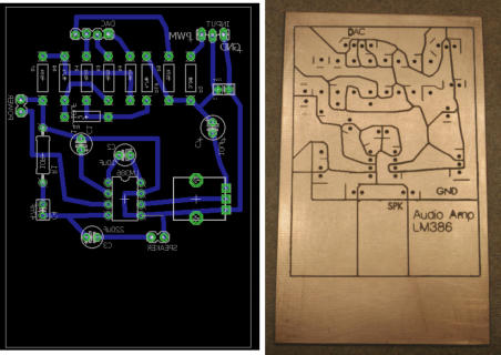
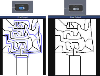
Here is an example: on the left we have a typical PCB with thin routes; on the right we have an Isolation PCB.
They both function the same, except the right one takes only about 10 minutes to make on any standard CNC
router and it doesn’t need any extra precision.
•
Eagle or other PCB design software that can export JPG/PNG with correct dimensions
•
Photo-Reactor to create Voronoi image and the PCB Tool flow
•
Software to turn the image into vector and create g-code toolpath (in our case Vectric)
We are skipping the whole creation of PCD design in Eagle. Let’s assume we already have the PCB design.
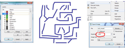
We need to export the routes as a PNG or JPG image. Set the background to white, then disable all layers and
leave only Bottom layer visible. Export to PNG image, but set the resolution to 1200 dpi (we want a large image)
When we are at it, hide the Bottom layer and enable the Pads layer. Export as another image (we will use this
later for drill marks). So we have two PNG images: Routes and Drill
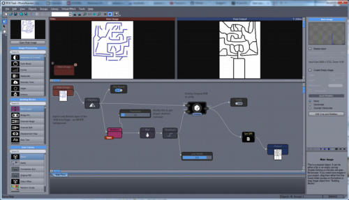
Now we need to turn the Routes into Voronoi. For that we use Photo Reactor with some cleverly designed flow.
Here is the flow zipped: PCB Tool. You need to unzip it and load in Photo Reactor.
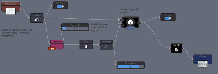
The flow has few interesting parts. First it will flip the board with Flip Board switch (because in Eagle we are
looking at the board from the top, but we need to make it from the bottom), then it can overlay the original and the
result voronoi to verify all is correct (Verify switch) and at last it needs to set DPI to the same as input image so
all will align in our CNC software with correct dimensions (nothing to set, it copies the input DPI to Output)
All we need to do is to load the flow in Photo Reactor, load the Routes image as Main Image (Open Main Image)
With Verify ON look at the result. The voronoi should cut the PCB correctly between the routes, if not you can
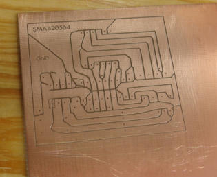
play with the threshold slider.. Then Switch the Verify OFF and do final Export (right image above). This is the
Voronoi image.
The rest depends on the type of software you are using to create CNC code. What you need to do is to vectorize
the image (if your CNC software doesn’t do it, you can use other software such as Illustrator, Inkscape etc…) and
then create toolpath from those vectors. Make sure you are not changing dimensions!
I am using Vectric software that came with my router. It vectorize images and creates toolpaths right there in the
same application. It keeps the correct dimensions from the imported JPG or PNG files. Very simple.
This is also the place where you may use the previously exported Drill image (don’t forget to flip it) to create
additional drill path. I am personally not drilling in the router (the chance of breaking the fine drill bit with my
clunky CNC is pretty high) but I am using the drill image to mark places for manual drilling with the very same
engraving bit I am using to route the lines.
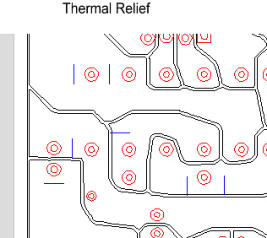
After vectorizing the voroni routes and before creating toolpath you may add some thermal reliefs. On the image
below those are the blue lines that will be routed alongside main lines. They will help with soldering to create
barrier for solder to stop. (it is not necessary and I don’t normally do it)
Here are some good values I use with my router. I am using 30 degree engraving bit (ebay) for both drilling
toolpath (but I am not actually drilling hole, just marking a little dot where I will drill manually)
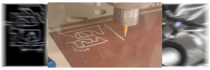
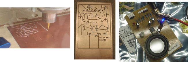
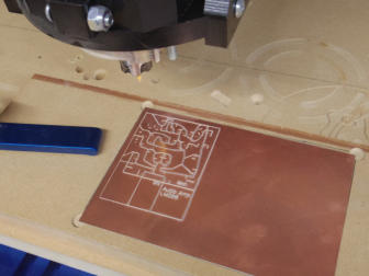
I created many PCBs with this method, some more complex than others and they all take about 10-30 minutes to
route depending on complexity. I have 100% success with a very clean cut and nearly professional look. The
usual post processing is to run large flat scraper few times over the routed board to level down the burr from the
bit, then use brass brush to remove any semi-loose shavings. Then manually drill the holes where marked.
Note: the biggest issue with CNC routing is to make sure the board sits flat on your CNC router table (and the
table itself is perfectly flat). The depth of the cut is only 0.005 inch so any little deviation in height will change the
depth of the cut. Little deeper than the thickness of copper is not a big deal (unless you cut through the board of
course), but little too shallow and you may not make reliable isolation line.


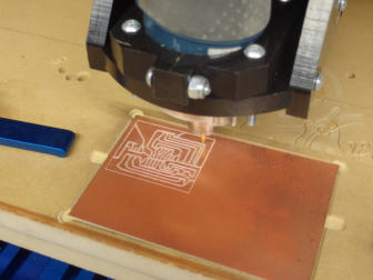
Using CNC router to make PCBs
PCB with CNC router
Isolation Voronoi PCB
Software used
Steps
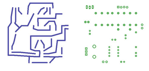
Routes
Drill
Thermal Relief
If you use Vectric software, here are the usual steps I take
•
Import the voronoi image for tracing
•
Trace bitmap (usually default works well)
•
Create new layer, import the drill image
•
Flip horizontally the drill image
•
Trace the drill image (in the new layer)
•
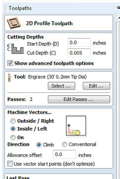
Create 2D profille toolpath for voronoi lines and
another Drill toolpath for the drill layer. Since I use
engraving bit vectric will not let it drill through.
•
Preview Toolpaths
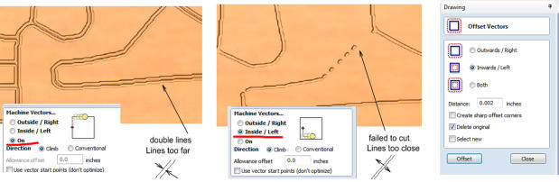
With toolpath preview in your CNC software you may check
the toolpaths and adjust the width of the lines. In my case
making toolpath inside the vectors instead of ON works best
but sometimes it is necessary to adjust the offset vectors.\
The goal is to have one routed line (that is created by the left
and right edges of the vectorized voronoi routes. If there is a
thin copper left in the middle, the edges are too far apart, if
there are spots where the router didn’t cut through the lines
are too close.
My usual settings is to expand the routed vectors once with
Offset 0.002 inch and set “Machine Vectors” Inside. But it
really depends on your CNC software how it deals with
vectors and how it creates G-Code.
Normal PCB
Isolation (Voronoi) PCB

Automatically turns a photo into painting inspired by real world artists
Dynamic image editor and effect processor with absolutely unlimited possibilities


Enhance Dynamic Range of your images for Eye- Catching results