Windows 7,8,10 (5MB)

THE ULTIMATE SOLUTION FOR WINDOWS MACROS


Version 2.28
DIY Keyboards
One solution for DIY project is to reuse Hid USB keyboard controller from existing keyboards. A keyboard chip works like a matrix of columns and rows to which a membrane for all keys is somehow attached. Unfortunately because of using membranes it is often hard to work with such controllers - you may have hard time to solder anything on the tiny traces. There are some controllers that offer easier way of attaching your own switches, for example we found out that many of the silicone roll out keyboards have a connector inside for attaching the membranes. If you are thinking about this route, you may explore the roll up keyboards (ask your friends, they will probably gladly give them to you)Project 1 - Rotary Dial
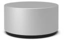
There is plenty of normal keyboards that one can salvage for Keyboard Macros, but there is a cool niche accessory that is in short supply: rotary dial. These dials have usually nothing to do with HID keyboards and require its own driver and software. A good example would be Microsoft Surface Dial. There were other similar devices made before at various times, but because they were not HID compliant nor there was any standard for rotary controller the software and drivers were never updated for new Windows and so these devices became quickly obsolete and unusable. Such dials can be used for example for Photoshop to change Brush Size or Zoom more comfortably than by keys, for video editing etc. In this project we are going to make a dial that is universal HID-compliant and doesn’t need driver. There are few ways how to approach such task. One would be to reuse a keyboard chip form an existing keyboard and create a rotary encoder that uses switches such as the cleverly designed (yet probably quite fiddly) 3D printed rotary encoder. However I am personally a big fan of Arduino project and I am aiming to build a more robust solution using a regular rotary encoder and custom made USB device. A normal Arduino (such as UNO) is very problematic to be used as an USB HID device without adding another USB controller and using virtual USB driver but there is one Arduino based on ATmega32U4 that has a full USB transceiver and can directly work as an USB HID-class device without any drivers. These 32U4 are under name Leonardo (large developer board) or Pro Micro (don’t confuse with Pro Mini) that was developed by Sparkfun that is small enough to fit into any device.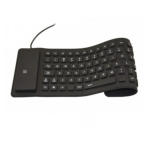
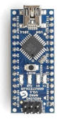
Arduino Nano
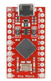
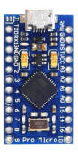
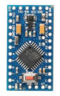
Arduino Pro Micro
Arduino Pro Mini


Arduino PRO Micro (32U4 ) 5V
The Pro Micro 5V is the ideal board for creating such USB Hid device. Make sure you get the correct one, there are other with similar names and looks such as Nano or Pro Mini that cannot be used this way. One way to quickly recognize PRO Micro is that they don’t have any mechanical button on the board while the others do. For a basic project we need two other components - a small switch that we will need to use as Reset Switch to program the 32U4 and a Rotary Encoder.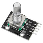
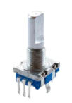
Rotary Encoder can be either on a board or as separate component.

Any push button switch would be fine
Breadboard
The purpose of this article is not to teach you how to use Arduino as there is vast amount of info on the web. The whole Rotary Dial project is incredibly simple - literally it is just an encoder and a switch. Working with Arduino requires you to know at least some basics - how to install Arduino IDE, libraries etc…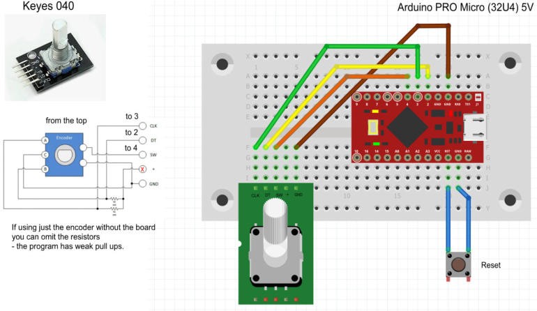
As you can see the “schematic” is incredibly primitive - the encoder could be either already populated on the board or just the component itself. On the image above you can see what the encoder
board has on it - it only adds pull up resistors and pins for easy connecting. Because arduino can use weak pullups in the software, we don’t actually need these resistors. In fact I plugged the
board without connecting the + pin of the board; which makes the external pull up resistors inactive.
The switch is used as Reset because Arduino Pro Micro doesn’t have reset button on the board. Unlike other arduinos that can be programmed without pressing reset as the bootloader handles all
for you, with Pro Micro the USB port has double duty. When it is in Bootloader mode it connects as a serial port and can be used to upload a program to Arduino. When it runs the uploaded sketch
it then behaves as an USB controller and at the same moment it cannot be programmed. Hitting reset will set the Pro Micro into bootloader mode for few seconds and that is the time you need to
upload sketch. So it may be a bit of timing game.
There is a good guide on sparkfun site how to install necessary board libraries as well as troubleshooting.
https://learn.sparkfun.com/tutorials/pro-micro--fio-v3-hookup-guide
Note, the need to press the reset button twice apply only for the red Sparkfun made Micro Pro. If you get the clone Micro Pro from Ebay then all you need to hit the Reset button once.
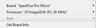
First time you are plugging PRO micro to your computer you need to select the correct board and also Port. It may happen that you can’t select the Port because the Pro Micro may already have a
sketch running (depends where you bought it) and so it is not in bootloader mode. You need to hit the reset button (or hit it 2x if it is the red Sparkfun PRO Micro) and go quickly to the interface to
select the port.
To upload sketch: What works for me is simply click upload button on the Arduino IDE, and then watch the status bar. It first says Compiling… then it will say Uploading at which moment I would hit
the Reset button. If all is right you will see Uploading Done. If not you will see red bar saying Couldn’t find Board on the selected port.

Hit Reset!
Once the Pro Micro is programmed with the sketch it will start working as an HID “keyboard”.
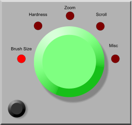
By default this sketch when you turn dial clockwise it will generate ‘]’ characters and counter clockwise ‘[‘
characters which actually is shortkey for photoshop brush size. When you press the rotary encoder switch it will
generate spacebar and hold it pressed until you release the encoder. (this maps to photoshop pan). You can
change these in the sketch if you need to, but using it with Multi keyboard macro means you can map it to anything
else later.
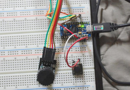
Once all works, you can then make it more permanent by soldering the encoder using short wires to the arduino
board. Don’t forget to put the reset switch as well in case you need to re-upload sketch or update it.
When you put your encoder in some sort of box, you may put the switch on the back or hidden where it won’t be
accidentally pressed.
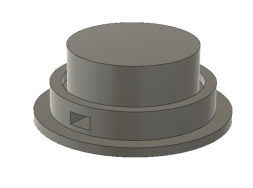
A good project would be to design and 3D print enclosure.
Arduino PRO Micro Sketch
Here is the sketch for the encoder
When it works correctly turning it clockwise should type stream of characters ]]]] and counter clockwise [[[[[
Notes: There are few types of encoders. A typical encoder would do its full quadruple cycle (four pulses) on a detent (click). Such encoder would be for example marked as 24 detents and 24
cycles. But there are encoders that will have detent on half positions as well - the Keyes 040 we had in this case was one of them (it is not guaranteed that all 040 will be half positions
encoders - it probably depends where you bought it). This encoder had 30 detents and 15 full cycles. In this case enable (uncomment) this line:
//#define HALF_STEP
Sometimes it is hard to determine if you have full cycle detent or half cycle detent encoder. You should leave the line commented (disabled) first and run it. If it works fine - each click in
direction will type one character, then you have full cycle and all is good. If you need to click twice in one directions to get one character typed then you have half cycle detents and you need
to uncoment the line above and compile upload again.
Once you have your working Dial and it sits in a nice box and has a nice knob, you can then program Multi-Keyboard Macros on it for your application as you would any other keyboard. by
default the [ and ] characters map to Photoshop brush size but of course with Multi Keyboard macros you can remap it to anything else for your graphics or video editing application.
The beauty of Arduino Pro Micro is that once programmed you don’t need any driver, just plug it to any computer as you would any keyboard.
Some future Ideas
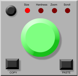
You can modify the schematics and sketch for more elaborate setup. For example you may add 4 buttons and 4 LEDs and when you press a button the encoder will use different keyboard set for the output - in which case you can map it to various other functions. You can add more buttons and map them to other keyboard keys. This would greatly increase the usability of such device even beyond what you can buy in store.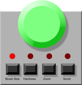


Ultra fast voice typing and voice commands - processed
entirely on your PC, in any application, forever.
No cloud. No monthly fee.

If you like Multi-Keyboard Macros - try our new Voice Macros!


About MediaChance
Products
Links